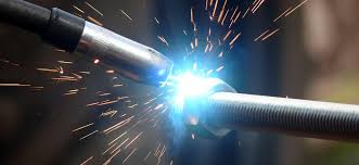
MIG MAG welding, also known as MIG MAG (Metal Inert Gas / Metal Active Gas) welding, is one of the most widely used welding processes in modern industry. Efficient, fast, and versatile, MIG MAG welding makes it possible to create strong, consistent, and durable joints on many types of metals.
TIG WELDING · MIG/MAG
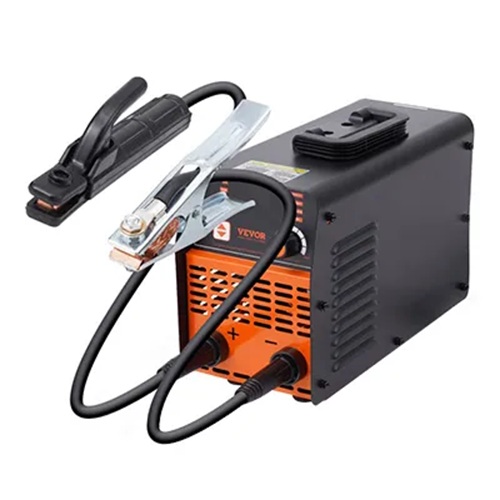
MMA · SPOT WELDING · DENT REPAIR
Reliable and verified links — available on Amazon & AliExpress
Through this page dedicated to MIG MAG welding, I guide you in understanding how the process works, mastering the essential settings, and improving the quality of your MIG MAG welds. Whether you are a beginner or a professional, this guide provides reliable and directly applicable information.
1. Introduction to MIG MAG Welding
MIG MAG welding is an arc welding process that uses a continuously fed consumable wire electrode combined with a shielding gas. In MIG mode, the gas is inert (argon or an argon–helium mix), while in MAG mode, the gas is active, generally based on CO₂ or argon/CO₂ mixtures.
MIG MAG welding is particularly appreciated for its high productivity, ease of use, and ability to be automated. It is widely used in metal construction, industrial boiler-making, and the automotive sector.
Difference Between MIG and MAG Welding
The fundamental difference between MIG and MAG welding lies solely in the type of shielding gas used to isolate the weld pool from the surrounding air. Although both processes use the same machine (a semi-automatic welder with continuously fed wire), their applications vary depending on the metal being welded:
- MIG (Metal Inert Gas) uses an inert gas, usually pure argon or an argon–helium mixture. This gas does not chemically react with the molten metal. It is mainly used for welding non-ferrous metals such as aluminum, copper, or magnesium.
- MAG (Metal Active Gas) uses an active gas, such as pure CO₂ or an argon–CO₂ mixture. This gas actively contributes to the process by stabilizing the arc and increasing penetration. It is the standard method for welding carbon steels (mild steel) and stainless steels.
Basic Glossary for Understanding MIG MAG Welding
To master MIG MAG welding, it is essential to understand the technical vocabulary that defines how the arc works and the quality of the weld. Everything relies on the wire electrode (or filler wire), which is stored on a spool and continuously fed through a wire feeder to the torch.
Here are the key terms to remember:
- The Weld Pool: The area of molten metal created by the heat of the arc where the wire and the workpieces mix.
- The Shielding Gas: Delivered through the nozzle, it protects the weld pool from atmospheric oxidation.
- The Contact Tip: A copper wear part located inside the torch that transfers electrical current to the wire.
- Wire Feed Speed: A crucial setting that determines both the welding current (A) and the amount of deposited metal.
- Voltage (U): Expressed in volts, it defines the arc length and the width of the weld bead.
- Spatter: Small droplets of molten metal expelled around the weld, often caused by incorrect settings or unsuitable gas.
- The Flowmeter: A device attached to the gas cylinder to regulate gas flow (usually measured in liters per minute, L/min).
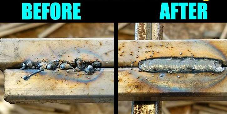
Poor understanding of the relationship between voltage and wire feed speed is the main cause of welding defects (lack of penetration or burn-through).
Likewise, a dirty contact tip can cause an unstable arc and excessive spatter.
2. Major Advantages of MIG MAG Welding
MIG MAG welding offers numerous technical and economic advantages. It provides excellent penetration, a high deposition rate, and great welding consistency, making it an essential process in industry.
Productivity and Efficiency of MIG MAG Welding
Thanks to the continuous feeding of the wire electrode, MIG MAG welding reduces interruptions and significantly increases production speed, especially for long and repetitive welds.
Advantages and Disadvantages of the MIG MAG Process
- Cost-effectiveness of the process
- Very high welding speed
- High metal deposition rate
Versatility of Weldable Materials
The MIG MAG welding process makes it possible to efficiently weld carbon steel, stainless steel, and aluminum by simply adapting the welding wire and shielding gas.
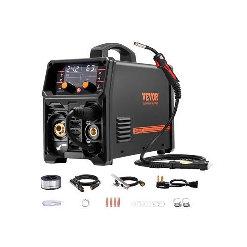
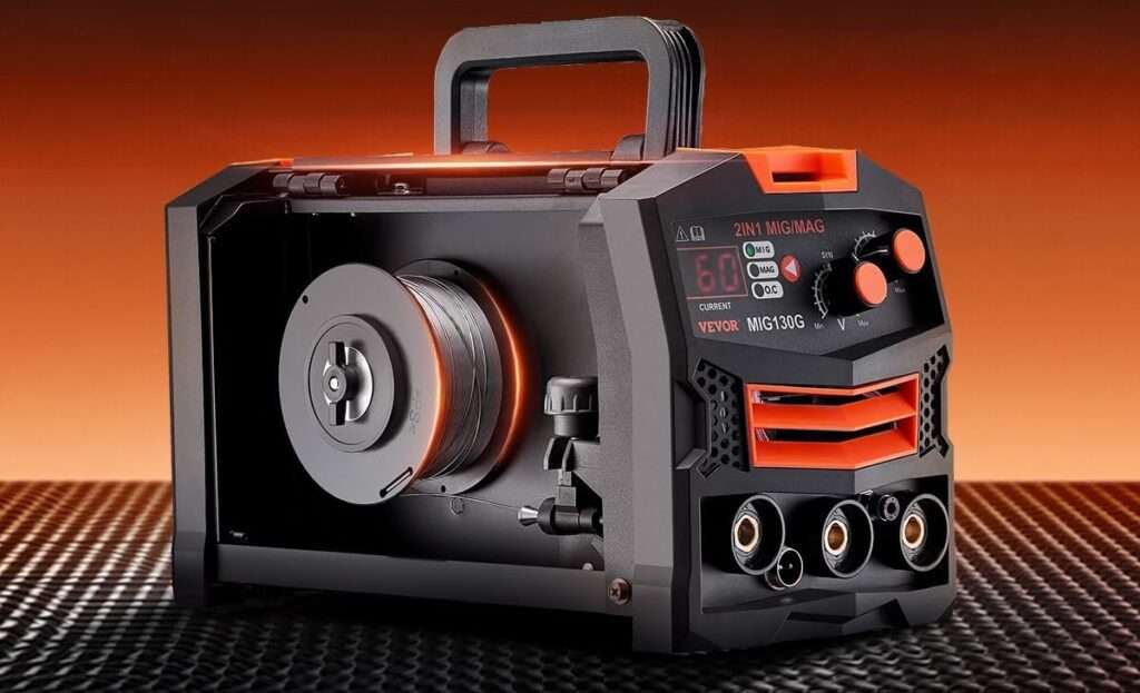
3. How a MIG MAG Welding Machine Works
The operation of a MIG MAG welding machine is based on creating an electric arc between the wire electrode and the workpiece. The wire melts under the heat and becomes the filler metal, while the gas protects the weld pool from oxidation.
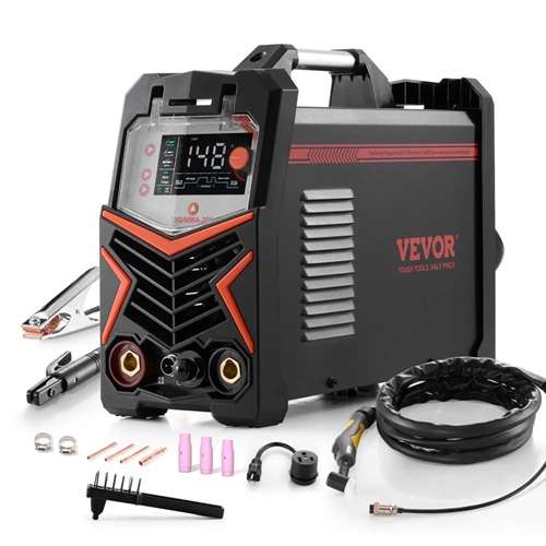
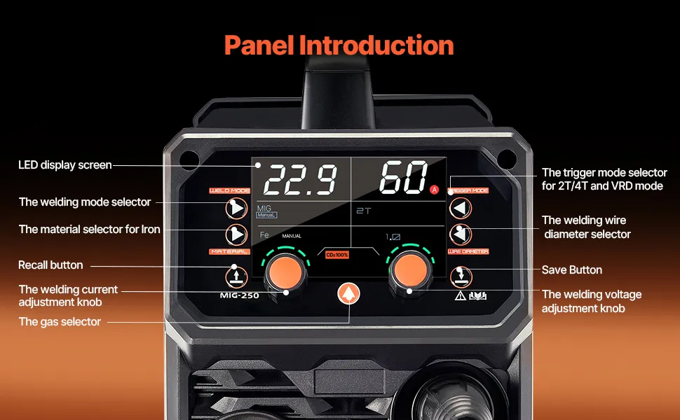
Key Components of a MIG MAG Welding Machine
A MIG MAG welding machine consists of a power source, a wire feeder, a MIG MAG torch, a wire spool, and a gas cylinder. Together, these elements ensure arc stability and high-quality MIG MAG welds.
4. Essential Settings for Successful MIG MAG Welding
Settings in MIG MAG welding are crucial for obtaining a consistent and strong weld bead. Voltage, wire feed speed, gas flow, and wire diameter must be perfectly adapted to the material and its thickness.
Key Points for Successful Adjustment
- Gas flow: A simple rule is to set your flow rate to 10 to 12 times the wire diameter. For example, for a 0.8 mm wire, a flow rate of 10 L/min is an excellent starting point.
- Nozzle rule: The distance between the nozzle and the workpiece (“stick-out”) should be around 10 to 15 mm. Too far reduces gas protection; too close increases nozzle contamination.
- Your ear is your best tool: A good setting in short-circuit mode (thin to medium thicknesses) should produce a tight, regular crackling sound, similar to bacon sizzling in a pan.
Workpiece Preparation
Remember that MIG/MAG welding is very sensitive to cleanliness. For optimal results in flat position:
- Grind the areas to be welded to remove scale or rust.
- Degrease if necessary.
- Tilt your torch about 10° to 15° in the direction of travel (push technique).
Setting Up Your MIG Welding Machine
Most modern welding machines are equipped with “synergy” mode. These are integrated parameters stored in the machine. After selecting several parameters (such as material, wire diameter, gas type, and thickness), the machine automatically chooses a voltage and wire feed speed, and may adjust them during welding. (The welder can still fine‑tune these settings.)
Other machines require manual settings. In this case, you choose the voltage and wire feed speed yourself and adjust them as needed.
The tables below provide general guidelines for the settings to consider.
Settings for Flat Welding Without Bevel
The settings of a MIG/MAG welding machine depend heavily on the thickness of the steel you want to weld. In flat welding (PA position), the goal is to find the balance between voltage (which controls bead width) and wire feed speed (which controls penetration).
Here is an indicative table for carbon steel (mild steel) using a standard gas mixture (Argon + 8 to 18% CO₂).
Indicative Settings Table (Flat Welding)
| Steel Thickness | Wire Diameter | Wire Feed (m/min) | Voltage (V) | Gas Flow (L/min) |
| 1 – 1.5 mm | 0.6 mm | 3.0 – 5.0 | 15 – 17 | 8 – 10 |
| 2 – 3 mm | 0.8 mm | 5.0 – 7.0 | 17 – 19 | 10 – 12 |
| 4 – 5 mm | 0.8 – 1.0 mm | 7.0 – 9.0 | 20 – 23 | 12 – 14 |
| 6 – 8 mm | 1.0 mm | 8.0 – 10.0 | 24 – 27 | 14 – 16 |
| 10 mm + | 1.2 mm | 7.0 – 9.0 | 28 – 32 | 16 – 18 |
Adjusting Gas Flow in MIG MAG Welding
The gas flow in MIG MAG welding protects the weld pool from ambient air. Insufficient flow leads to welding defects, while excessive flow creates turbulence and unnecessary gas consumption.
Welding with CO2 Gas (Pure CO2)
- Low cost.
- Low sensitivity to oxidation, except on the surface.
- Good weldability on oxidized sheets.
- Few spatters in short-circuit mode.
- High penetration.
- Poor weld bead appearance.
- More delicate settings compared to other gases.
Welding with Argon+CO2 Gas (Binary Gas)
- Fairly simple settings.
- Good weld bead wetting.
- Hotter weld pool.
- Commonly used mixture.
- Higher cost than other gases.
- Sensitive to humidity and oxidation.
Gas Selection and Its Influence on the Weld Bead
The choice of shielding gas depends on the welding mode. For short-circuit mode, CO₂ or Argon+CO₂ is preferred, while pure Argon should be avoided. In globular transfer mode, which is intermediate, all three gases can be used. For spray transfer mode, CO₂ should be avoided in favor of pure Argon or Argon+CO₂ mixtures.
MIG MAG Gas Flow: Indicative Values
- Thin sheet (1–2 mm): 8 to 10 L/min
- Medium thickness (3–5 mm): 10 to 12 L/min
- Thick material: 12 to 15 L/min
- Outdoor welding: 15 to 18 L/min
Factors Influencing Gas Flow
- Diameter of the MIG MAG torch nozzle
- Wire electrode stick-out
- Welding position
- Work environment (drafts, wind)
Common MIG MAG Welding Errors
- Insufficient gas flow causing porosity in the weld bead
- Incorrect voltage / wire feed settings causing spatter
- Wire unsuitable for the welded material
- Clogged nozzle disrupting gas protection
- Travel speed too fast or too slow
5. Professional Applications of MIG MAG Welding
MIG MAG welding is widely used in the automotive industry, metal construction, steel frame manufacturing, heavy boiler-making, and industrial maintenance. Its productivity makes it a reference process for large-scale production.
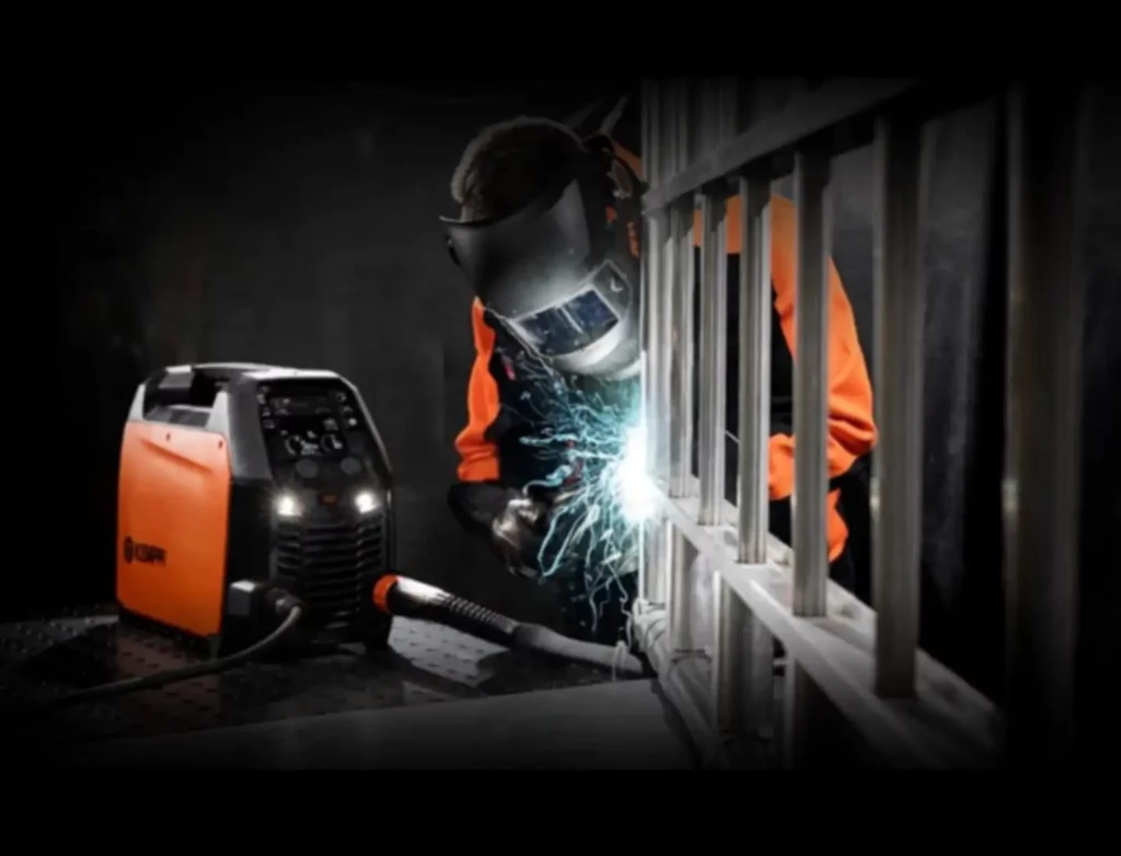
6. Safety and Best Practices in MIG MAG Welding
MIG MAG welding requires strict compliance with safety rules. Wearing personal protective equipment is essential: welding helmet, insulated gloves, flame‑resistant clothing, and appropriate respiratory protection.
Welding by Pushing or Pulling
In MIG MAG welding, you can weld by pushing or pulling the torch. Although each method has its advantages and disadvantages, welding by pushing is generally considered the most suitable technique for achieving a clean and controlled weld when possible.
Welding by Pushing (Push Technique)
The workpiece is well preheated by the arc, which improves wetting. The weld pool is more visible because it is not hidden by the torch. The weld bead is wider and flatter (with less penetration). When pushing (at an angle of around 70 to 80°), the bead tends to be flatter.
Welding by Pulling (Pull Technique)
In this welding configuration, the weld pool is very hot, very fluid, and difficult to control. The weld bead becomes more convex and penetration increases. The weld pool is harder to see because it is hidden by the torch. When pulling (at an angle of around 70 to 80°), the bead tends to be more convex and penetrating.
Training and Expertise of a MIG MAG Welder
A skilled MIG MAG welder stands out through mastery of machine settings, knowledge of materials, and the ability to adapt parameters to constraints. Continuous training is essential to ensure reliable MIG MAG welds that meet professional standards.
7. MIG MAG FAQ
Conclusion: Why Choose MIG MAG Welding
MIG MAG welding stands out as an essential welding process for professionals seeking productivity, versatility, and quality. When properly adjusted and mastered, it enables strong, durable welds perfectly suited to modern industrial requirements.